How to integrate ADS1015 with Arduino in Simulink?
ADS1015 is 4-channel 12-bit ADC converter made by Texas Instruments that is simple in use, quite cheap and enough accurate. Moreover, Adafruit provides it with breakout boards and libraries for Arduino and Raspberry Pi, so it seems to be great tool to learn for every beginner. Additionally, big advantage of this chip is that you can use both I2C and SPI as communication protocole.
All necessary information about this ADC converter you will in official documentation:
https://drive.google.com/folderview?id=0B3V80Kki3bnMcjhpZGlMSWNnZTQ&usp=sharing
I highly recommend to look deeply into the Arduino libraries provided by Adafruit:
https://github.com/adafruit/Adafruit_ADS1X15
https://www.adafruit.com/products/1083
If we are enough prepared, we've tried to run the example code on our Arduino I guess we can start working on Simulink.
What you will need:
-
Arduino Mega - reads data from ASD1015 converter. Arduino Mega enables to use External Mode and that means that you can analyze the data online on the scope.
-
ASD1015 - 4-channel 12-bit analog to digital converter.
-
Potentiometer – simple tool to test analogue inputs.
Step by step, follow these instructions:
-
Create new folder for your project.
-
Go to ADS1015 Arduino Library and copy "Adafruit_ADS1015.h" and "Adafruit_ADS1015.cpp" to your folder.
-
Open Arduino IDE and find Example Program for ADS1015 - "singleended" (a reference code in Simulink).
-
Open Tools → Run on Target Hardware → Prepare to Run…
-
Select Run on Target Hardware.
-
Tick Enable External mode (Remember that Arduino Uno doesn’t support External Mode, so it’s better to get Arduino Mega).
-
Select External from the main toolbar.
-
Enter “inf” in Simulation Time field.
-
Save Simulink Model in proper folder.
-
Open Simulink Library Browser.
-
Select S-Function Builder and drag it to Simulink Model.
-
Open S-Function Block and Initialization tab.
-
Enter “1” in Number of Discrete states. Select Discrete in Sample mode and enter 0.05 as Sample time value.
-
Open Data Properties tab.
-
Add four output ports: A0, A1, A2 and A3.
-
Open Data type attributes tab.
-
Change Data type to int16.
-
Open Libraries tab and Open Arduino IDE and look at the Example code.
-
Enter:
#ifndef MATLAB_MEX_FILE
#define ARDUINO 100
#include “Adafruit_ADS1015.cpp”
Adafruit_ADS1015 ads;
#endif
21. Open Discrete Update tab.
22. Enter:
if(xD[0] != 1)
{
#ifndef MATLAB_MEX_FILE
ads.begin();
#endif
xD[0] = 1;
}
23. Open Outputs tab and Open Arduino IDE and look at the loop function.
24. Enter:
#ifndef MATLAB_MEX_FILE
if(xD[0] == 1)
{
A0[0] = ads.readADC_SingleEnded(0);
A1[0] = ads.readADC_SingleEnded(1);
A2[0] = ads.readADC_SingleEnded(2);
A3[0] = ads.readADC_SingleEnded(3);
}
#endif
25. Enter the name of S-Function.
26. Click Build.
27. Open Matlab main screen.
28. Open wrapper function (sfADS1015_wrapper.c)
29. Add extern “C”, before every function.
30. Save file and change its type to .cpp.
31. Open Simulink Model.
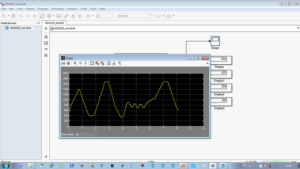
32. Add necessary blocks to the Simulation (scopes, display values, etc.).
33. Remember that the output ports have format int16.
34. Open Tools → Run on Target Hardware → Run…

ADS1015 integrated with Arduino and Simulink
ADS1015 integrated with Arduino and Simulink

Potentiometer
ADS1015 integrated with Arduino and Simulink
YouTube movie that shows in practice how to program Arduino in Simulink to read data via I2C from ADS1015: